Routing considerations with double patterning: Certain decisions affect whether a methodology is DP-compatible.

By David Abercrombie
In my last article, I reviewed the aspects of cell design that are affected by double patterning (DP). This time, I’ll discuss how automatic routing is affected by DP. Let’s begin by looking at the interaction between decisions made at the cell design level and decisions made at the routing level.
One key routing decision is whether or not you will allow cell-to-cell routing on the pin metal layer. In other words, will you allow the router to make connections from pin-to-pin between cells on the same metal layer on which the pins reside? If the decision is “yes,” then the methodology that determines the constraints on pin coloring during cell development needs to be reviewed for DP compatibility.
Pin coloring in the cell can be affected in two ways. If the pin polygons are “pre-colored” or “anchored,” then their color is constrained to the specified colors. Even if the pin colors are not pre-determined, spacing interactions with other polygons in the cell may define certain color differences between pins. Figure 1 shows how spacing interactions within the cells can force certain color differences between various pins in various cells.

Figure 1: Cell-to-cell routing limitations due to forced color differences on the cell pins.
Given these pre-determined colors or forced color differences, conditions may exist that constrain cell-to-cell routing. In Figure 1, the pins in neighboring cells that exist on the same routing track are forced to different colors by their spacing constraints with respect to other polygons. This color difference makes it illegal to connect them using the same metal layer, because the resulting merged polygon cannot be placed on a unified color. DP methodologies at the cell level must be aligned with DP methodologies at the routing level to assure optimal results.
When dealing with layers purely dedicated to auto-routing, it might seem that DP would be similar to other DRC rules, in that DP rules must be included in the router technology file and adhered to by the routing engine. The big challenge for routers, however, is that DP violations are not short-range issues. Most DRC checks are easy for the router to check and avoid, as they only involve a single polygon or a nearest neighbor. These conditions can be quickly measured, and their solutions are easy to determine. DP cycle violations, on the other hand, can involve hundreds or thousands of polygons, and can extend across the full chip. In addition, each violation has numerous alternative fixing solutions. Figure 2 shows both local and long-range cycle violations in a routed layout.

Figure 2: Local and long-range DP cycle violations in routed layout.
The compute processing needed to verify such long-range potential DP violations and determine optimal fixes is counter to the goal of high-speed automated routing. That is not to say that modern routers do not include DP cycle checking in their engines, but you should set your expectations accordingly in regards to both the impact on runtime and the potential to find unresolved errors in post P&R verification runs.
Luckily, encoding DP checking into the router is not the only technique available to help automated routing produce DP-compliant layouts. Advanced automated routing tools like Mentor Olympus-SoC now incorporate DP prevention and repair techniques in their arsenal.
The idea behind the prevention technique is to enforce simpler constraint rules during the routing phase that inherently reduce the possibility of creating a DP cycle violation. Examples of such “restricted routing” rules include:
These rules are easily enforced by the routing engine, and reduce the possibility that a DP cycle violation will be created. Of course, there is a trade-off. Extensive use of such rules constrains the flexibility of the routing solution, can force an increased use of vias and extra routing tracks on other layers, and may increase the chip area. Figure 3 shows the results of an experiment in which some restricted routing rules were used to avoid DP violations.

Figure 3: Experimental results of routing a chip using restricted routing rules to avoid DP violations.
As demonstrated in the experiment, there was a significant increase in both the total wire length and number of vias used in the chip. Both of these changes can increase yield sensitivity and, potentially, die area. Although the occurrence of DP violations was rare utilizing these restricted rules, their use still did not guarantee complete avoidance of DP violations.
The bottom line is that nothing comes for free, and even the best efforts of the best routers in the world may not completely ensure a DP-clean route on first pass. It always will be necessary to run a full production verification engine such as Calibre on the routed layout to look for violations that the routing engine didn’t detect. This is precisely why Calibre has integrations with all the major routers, and in-memory integration with Olympus-SoC (using Calibre InRoute).
However, while Calibre will make sure you don’t miss a DP violation, the challenge for the routers is doing something useful with that information. This is where the repair technique comes into play. Finding and fixing errors detected by sign-off verification tools is not something new for routers. Designers have used repair flows based on Calibre error marker databases for a long time. The typical approach for the router is to perform a re-route within a “halo” (expanded area) around the error marker, and then re-check the changes in the halo to make sure new errors are not introduced. This works very well for the majority of DRC rules. There are challenges, however, in using this approach with DP cycle violations.
Figure 4 demonstrates a flaw in this traditional approach for DP cycle error correction. The original odd cycle in this example is relatively localized, and a traditional halo region around the error seems sufficient to implement a repair solution and recheck for validity. In the repair, the error appears to be corrected successfully if only the halo region is re-checked. However, a new cycle violation is introduced that extends far beyond the original halo region.
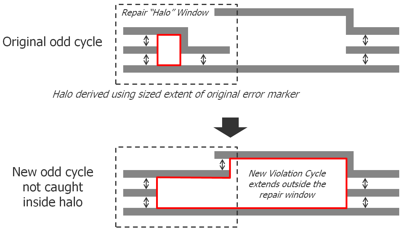
Figure 4: DP cycle violation repair and missed new error using a traditional halo region.
One fairly obvious extension to the traditional flow that would seem to help with this issue would be to expand the derivation of the halo region. Figure 5 shows the results of extending a halo region around the extent of the polygons involved in the original error, rather than just the area around the original error marker. It is clear that this approach might help resolve the original DP violation, and even the first additional error cycle, but now a new error is formed that extends beyond the bounds of even this expanded halo region. In short, there is no “halo” definition that will guarantee re-validation of a routing DP fix unless it extends to cover the whole chip.

Figure 5: Modified solution redefining the halo region as the expanded extent of the polygons involved in the original error still leads to a missed new violation.
With this in mind, some have proposed an alternative method in which coloring is arbitrarily generated during the checking pass, then carried into the halo fix and re-validation pass as a means to look for new errors. Once the fix is applied, the router simply checks to see if the newly moved polygons generate a same-color spacing violation. In this case, however, the router incorrectly rejects the fix (Figure 6).

Figure 6: Use of color information within the halo region to re-validate a routing fix leads to a false DP error.
Although the router does find a new DP error, it is, in fact, a false error, in that the color of the top polygon was arbitrarily assigned to blue. It can be changed to green with no consequences, making the original fix valid. For that matter, the three lower polygons could be flipped to green-blue-green instead of their current blue-green-blue, also making the fix valid. In short, the arbitrary color assignment approach severely restricts the DP solution space.
In the end, DP-aware and DP-compliant automated routing is no easy task, but that doesn’t mean you can’t be successful. Advanced routers like Olympus-SoC do a very good job of utilizing integrated DP checking, restrictive routing rules, and automated fixing of Calibre errors to try and obtain the best result possible with reasonable run times. However, you need to expect some iteration using a sign-off verification tool like Calibre. You also must align your cell design methodology with your routing methodology in regards to DP. The more you learn, experiment, and prepare, the better off you will be. That is why I write blogs like this, in hopes of helping you along in that process.
In my next article, we’ll look ahead at the new multi-patterning challenges we might expect to see at 10nm and below.
 |
|
 |
|
 |
 |
 | |
 |
 |
Leave a Reply