Getting started with portable stimulus at the block, subsystem, and system levels.

Over the past few years, lots of energy has been invested in improving the productivity and quality-of-results of design verification. A promising effort toward this end is that both commercial and in-house tools have been developed to improve the productivity and efficiency of verification at the block, subsystem, and system levels. These tools raise the level of abstraction, increase test-generation efficiency, and are applicable across a wide variety of verification environments.
This effort has heightened interest in bringing automated tests to verification environments that go beyond transaction-oriented, block-level environments, along with a concomitant interest in having a standardized input-specification language with which to specify these tests.
In response, Accellera launched a working group, titled the Portable Stimulus Working Group (PSWG), to collect requirements, garner technology contributions, and specify a standardized input language that can be used to specify test intent that can be targeted to a variety of verification platforms.
Features of the Accellera PSS input specification enable test intent to be retargeted to different environments, while the core of the description remains environment independent. Random fields and constraints can be easily brought in from existing SystemVerilog descriptions and key components of the standard can be adopted incrementally, making it easy to get started.
So how do you go about targeting these different platforms? This article will show you how to get started using portable stimulus to automate testing at the block, subsystem, and system levels.
There is an enormous benefit to applying portable stimulus in block-level verification environments. Portable stimulus tools require very efficient and targeted test generation, because of the requirement to efficiently generate tests for SoC-level environments. In a block-level environment, efficient test generation achieves functional coverage goals more quickly and finds bugs earlier in the verification cycle.
The example used in this article is a multi-channel DMA engine. As is typical with DMA engines of this type, memory-transfer operations are characterized by a transfer descriptor that captures the transfer size, source and destination addresses, address increment settings, and detailed transfer options. At the block level, we want to comprehensively exercise combinations of these transfer-descriptor fields in order to comprehensively verify the DMA implementation.
A simplified view of the UVM testbench surrounding this IP is shown below. The DMA engine is exercised using a UVM sequence that programs registers within the DMA engine according to a DMA descriptor class.

Figure 1: Simplified UVM testbench.
The DMA descriptor class contains fields and constraints that define a valid DMA transfer. The ability to leverage this existing description from a portable stimulus description is important, since an engineer has invested time to correctly capture the constraints, and since the rest of the environment is driven by this class. Fortunately, the transaction-level subset of Accellera PSS overlaps with the SystemVerilog constraint subset to an extent that many SystemVerilog constraint-based descriptions can be converted to PSS descriptions.

A comparison of the original SystemVerilog class and PSS struct is shown above. Importing the SystemVerilog description and making it available inside a PSS description leverages the effort invested in creating the sequence-level description in SystemVerilog, makes getting started with PSS easier, and ensures that the PSS description stays in sync with any changes made to the sequence item on the SystemVerilog side.
Now we will describe the most basic DMA operation: a DMA transfer. In a portable stimulus description, the data and behavior of an operation is encapsulated in an action.

As shown above, an action is declared within a component, which encapsulates resources shared by multiple actions. At this basic block-level of verification, we don’t need anything special in our wb_dma_c component. Our do_dma action simply captures a random wb_dma_descriptor struct field. We’ll fill in the implementation details later.
From a test perspective, one of the first things we might want to do is simply generate a series of single DMA transfers. We describe our testing scenarios inside actions, just like our primitive operations. Since our test scenarios are themselves composed of actions, we add an Activity Graph (keyword: activity) to specify the relationships between sub-actions.
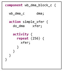
Note that we declare our simple_xfer action within a component. This component contains an instance of the wb_dma_c component that declares the do_dma action. Our simple_xfer action simply runs 256 repetitions of the do_dma action.

We might want to extend our testing a bit to perform two back-to-back DMA transfers, with the constraint that the channel used by the two transfers are different. This should provoke more-interesting activity within the DMA controller. Note how we can constrain the random fields of an action instance from above — something that is challenging to do with a directed-random sequence.
Thus far, we haven’t worried much about how our actions will connect to the UVM testbench environment. The type extension capability provided by PSS makes it easy to layer in our interface to the environment without needing to change any of the actions or components we’ve already described.
In our UVM testbench, stimulus is driven by a UVM sequence that generates wb_dma_descriptor sequence items. We’ll want to integrate our PSS description inside a UVM sequence and also have it generate wb_dma_descriptor sequence items — but with the field values selected by our portable stimulus tool instead of using regular SystemVerilog constrained random.

PSS packages provide a great way to encapsulate environment specifics, and we use a package here to contain the specifics of how our do_dma action will integrate with our UVM sequence. Specifically, we assume our sequence provides a task named do_item that accepts and executes a wb_dma_descriptor sequence item. The import statement specifies the signature of this external method.
Next, we need to specify how the do_dma action uses this imported method. PSS provides exec blocks to specify the relationship between PSS entities and external code. The body type of an exec block specifies execution-time behavior (much as the UVM sequence body task does). In this case, we specify that the execution-time behavior of the do_dma action is to pass the wb_dma_descriptor field to the do_item task.

Figure 2: Implementing a PSS sequence to drive the UVM testbench.
Our new PSS-drive UVM sequence can now drive the UVM testbench, with the advantage that we can much more efficiently exercise the DMA transfer modes.
At the subsystem and SoC levels, both what is verified and how it is verified change. Now instead of focusing on verifying the implementation of the DMA engine, we’re more interested in how the DMA engine is integrated with the other blocks in the subsystem or SoC. What’s also different, especially at the SoC level, is that we have an embedded processor, and we will want to drive at least some test activity with code running on that processor.
For a subsystem-level environment, we might start with a block diagram similar to what is shown below.

Figure 3: A simplified subsystem.
The DMA engine is now in the context of a subsystem that includes a processor (stubbed out with a bus functional model) and other IP.
Bringing our PSS description forward into this subsystem/SoC environment can be done in two steps:
The goal of this environment is to verify the integration with the other IP in the subsystem. To do so, we will run multiple, parallel DMA transfers. The first thing we will do is extend our dma_c component to specify the resources available — in this case, 31 DMA channels. Also, we will create a new action type that consumes a DMA channel and specifies its data-flow requirements.

Our updated DMA component and action now specify:

Filling in a bit more detail, we create an aes_c component to model operations on the AES block. Note that the do_encrypt action takes a memory buffer and that we’ve forced the address of input data to be the buffer address of the AES block. Constraints on the membuf_s input are bi-directional, so this constraint forces the DMA to target the AES device when a do_mem2mem_dma action sends data to a do_encrypt action. We also use a resource pool in the aes_c component to specify that only a single operation can occur on the AES block at a given time.
Finally, we specify a component to represent our system that specifies the available resources (DMA and AES blocks), and we specify a top-level action to perform parallel DMA transfers. Note that we’ve only captured the fact that we want to perform four parallel DMA operations. This is a partial specification: we don’t specify where the data should come from, or where it should go. The PSS processing tool will infer and connect the appropriate actions to ensure legal scenarios are generated. Specifically:
Partial specification is an incredibly powerful technique for generating complex test scenarios from a simple, concise specification.
In our subsystem-level environment, where DMA transfers are still driven by a sequence, we can reuse the same style of integration with the UVM environment that we did in the block-level environment. At the SoC level, our test will use utility functions written in C to program the DMA. In many cases, these utility functions will be the beginning of driver routines to later be used within an OS driver. Having our integration tests call these same utility routines provides an additional level of confidence in these utility routines, as well as exercising the integration of hardware IP.

Just as with our block-level environment, we can extend our core PSS description to layer in the environment specifics. In this case, we describe the C API that we will call (wb_dma_drv_single_xfer), and we provide the definition of an exec block for the do_dma action that calls this API and passes values from the DMA descriptor.
Portable stimulus tools help to raise the level of test description and enable modeling of scenarios that would be very challenging to create with directed and transaction-level constrained random tests. As a result, they enable automated creation of more unique tests.
The next time you face a verification task that exceeds the capabilities of directed or constrained random tests, think about applying portable stimulus.
To learn more about how to quickly start using portable stimulus to increase your verification productivity, please read the whitepapers, Smoothing the Path to Software-Driven Verification with Portable Stimulus and Automating Tests with Portable Stimulus from IP to SoC Level.
 |
|
 |
 |
 |  |
 |  |
Leave a Reply