Constraints have become much more than just physical dimensions.

Since the dawn of PCB usage, constraints have been an important part of the design. What are the dimensions? What weight of copper? Now, constraints have become much more than just physical dimensions. The most important constraints are defined by the design requirements of differential pairs, BGAs, low voltage devices, and high-speed parallel interfaces.
The cost of rework skyrockets the further out in the design process a fault is discovered. Ideally, a “correct-by-design” methodology would allow constraints to be rigidly followed, eliminating the possibility of error as the design progresses. In the real world, verifying signal integrity early is important to ensuring that all constraints have been met.
Constraint entering
One of the issues that often makes constraint setup tedious and time-consuming is a poorly designed user interface. Having to open multiple windows without being able to see all your constraints at once is confusing, error prone, and forces you to manually update each constraint one at a time.
More modern design tools provide significant benefits over traditional, dialog-based approaches by using a spreadsheet-based approach to make it easier to capture and review constraints.
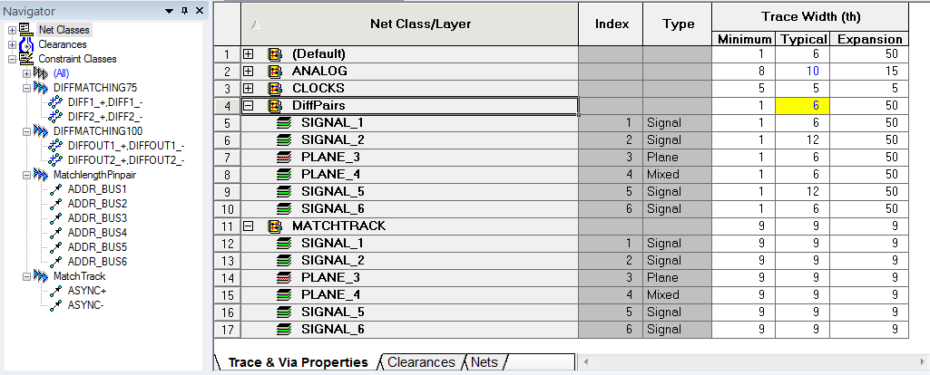
Figure 1: Constraint management can be complicated, especially with traditional dialog-based environments. A spreadsheet-based approach simplifies the entire process.
Powerful spreadsheet editing features, such as multi-row/multi-column copy/paste and auto fill, allow large numbers of constraint values to be captured or modified quickly. Opening two instances of the Constraint Manager allows constraint values to be copied from one project to another, thus providing constraint reuse capabilities.
Defining Constraints
There are several constraints that may or may not be useful for a particular design project. Common design constraints include the following:
1. Topology constraints restrict routing patterns for particular nets. They are used to control the routing structure and to impose length restrictions on net branches (pin pairs). Two common constraints are topology type and maximum stub length.
The topology type can set no restrictions to the routing or restrict routing in a defined way. The max stub length constraint applies to net types with constrained topologies. It restricts the length of traces shared by adjacent net branches. Both constraints can be specified at the constraint class level or be overwritten for individual nets.
2. Length constraints impose restrictions on routing length for nets and net branches and include minimum length, maximum length, and matched length. Minimum and maximum length constraints can be assigned to a constraint class, individual net, or to an individual net branch (pin pair). To define a matched-length constraint, a matched length group is required. This approach establishes a restriction on relative lengths of group members, i.e. the length difference between any two-group members should not exceed the specified tolerance value. A matched-length group can include either nets or net branches (pin pairs). Mixing nets and pin pairs in one group is not allowed.
3. Routing constraints impose restrictions on routing layers, via usage, and trace width. Routing constraints are defined at the net-class level and are applied to all nets in the net class. They impose restrictions on routing layer usage, on via types allowed for routing, and on the allowed trace-width range.

Figure 2: This example spreadsheet view from Mentor Graphics PADS Standard shows constraint types that can be specified for individual branches of nets with custom topology. Shown here are matched-length restrictions and a stub-length violation.
4. Clearance constraints define a minimum allowed clearance between edges of two routing objects (such as traces, pads, and copper areas) on a particular routing layer.
5. Differential pair constraints include trace width, differential spacing, and maximum separation distance. The maximum separation distance, which specifies how long traces can run parallel while violating the differential spacing value, is layer-independent.

Figure 3: Differential pair constraints.
6. Power supply net constraints – tools like PADS automatically recognize power supply nets based on pre-defined standard names, such as GND, VCC, +5V, -12V, etc.
Grouping
Proper grouping and definition of net classes and constraint classes in the early stages of the design process simplify constraint definition and management significantly. Grouped constraints can increase layout efficiency, reducing design time and, ultimately, saving PCB design costs.
Net classes are used to organize and speed the definition of routing constraints for nets with similar characteristics. For a net class you can define the layers allowed for routing, the corresponding trace-width range for these layers, and the via types allowed for nets in the net class. For differential pairs, you can define a layer-dependent differential pair gap.
Constraint classes are used to organize and speed the definition of length, topology, and other constraints for nets with similar electrical and timing properties. Although constraints assigned to a constraint class are applied automatically to all nets in the class, particular constraint values can be customized for individual nets, pin pairs, and differential pairs.

Figure 4: Constraint classes eliminate the need to create length and topology constraints for individual nets.
Differential pairs are groups of two physical nets implementing a differential signal. As the number of differential pairs increases, it becomes tedious to define the pairs one at a time. Automation makes it easy to create differential pairs quickly and easily. Net names typically follow patterns. Use these patterns to find the net names you want to assign as differential pairs. A list of proposed differential pairs is displayed; uncheck the matches that you don’t want to assign.
Reviewing Constraint Violations
Traditionally, constraint violations are checked and reviewed inside your layout tool. Some newer tools support constraint violation viewing inside layout or inside the constraint management environment. By viewing violations in the environment where the constraints were defined, the process is accessible to engineers and designers alike and more natural to the work flow.
Summary
Constraint management should be intuitive, quick and easy, and designed specifically to fit designers’ everyday work processes. A unified approach ensures a correct-by-design methodology and eliminates errors caused when separate constraint management tools are used in the schematic and layout environment. All constraints should be synchronized and accessible throughout the flow.
To learn more about constraint management and Mentor Graphics PADS click here.
 |
|
 |
 |
 |  |
 |  |
Leave a Reply