Why it’s so difficult to model noise for MEMS condenser microphones.

We are seeing a lot of interest in simulating noise, particularly for condenser microphones. With any transducer, noise reduction is always a plus, and with microphones there are two specific applications that need low noise. One is where the microphone is positioned away from the sound source, such as in video calling or when using voice commands with tablet computers. The other is where multiple microphones are positioned in an array, to detect the direction of incoming sound or for noise canceling applications.

Figure 1: A Section of a MEMS Microphone Model
Noise Sources in MEMS Microphones
All microphones generate noise, in the electronics, the package and the sensing element itself. In a MEMS condenser microphone the noise of the sensing element is dominated by thermal noise (also referred to as Johnson-Nyquist noise) created by the flow resistances of the sound port, back plate perforation holes and diaphragm vent holes. Physically, the origin of the thermal noise is the random motion of the molecules of air associated with these the flow resistances. The molecules of air generate movement of the diaphragm which is converted to an electrical signal by an electronic circuit. In practice, the level of noise generated is closely linked to the sensitivity of the microphone: less noise comes at the expense of a lower sensitivity and vice-versa. For this reason, the Signal to Noise ratio (SNR) provides a good indication of performance. The SNR is the difference in decibels between the noise level and the sensitivity under a 1 kHz, 94 dB SPL (1 Pa) reference signal.
Designing MEMS Microphones
MEMS condenser microphones are quite challenging devices to model. In most cases you have non-linear coupled physics to deal with, and complex geometry in the highly perforated back plate. The conventional approach is to linearize the system and use an equivalent circuit model. This approach works, though it requires a high level of modeling expertise, often to the Ph.D. level, to create and maintain the model. Here’s a thought. Rather than build an equivalent circuit model why not just simulate the SNR directly? All you need is to have is the right mix of elements and simulator to do the job. For those not already using the MEMS+ module of CoventorMP, hopefully you’ll be interested to know we’ve had this capability for a number of years using our integration with Cadence Spectre. With the next MEMS+ module of CoventorMP due out in Spring 2018, you will also be able run a noise analysis using the MEMS+ simulator. We are really proud of this new leading edge simulation capability for MEMS device designers.
To understand how our solution works, please take a look at the diagram below (Figure 2). This shows a hybrid condenser microphone model. The membrane and back plate are modeled using our multi physics finite elements. Lumped elements are used for the vent hole, back-chamber and the sound port. If you’re only looking at the sensing element (i.e. no attached electronics) you can directly run a simulation in MEMS+ and/or MathWorks MATLAB.

Figure 2: Diagram showing MEMS+ hybrid model comprising distributed finite elements and lumped elements. All dissipative elements act as thermal noise sources.
Using either tool, you can predict the sensitivity and noise of any output field. For noise, this could be displacement noise, or more usually capacitance noise. The latter can be easily converted into a voltage noise and then integrated across the audio band with an A-weighting filter. Then, it’s a simple step to combine the noise with the sensitivity to get the SNR value.
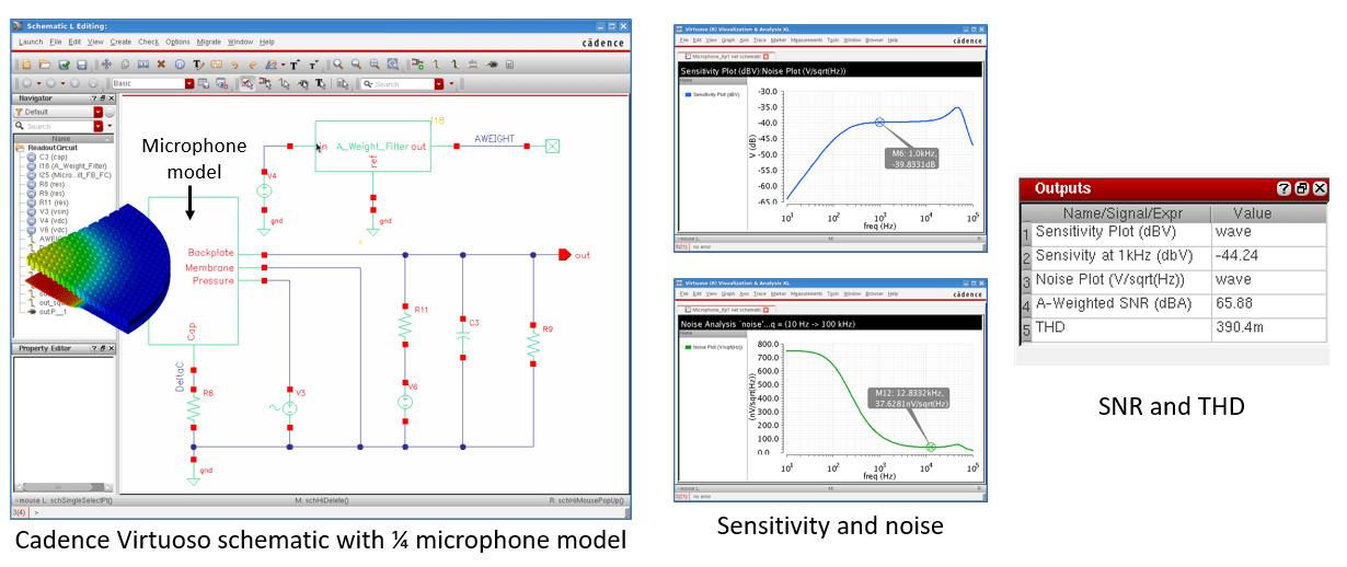
Of course, you might want to go a step further and model the electronics with the sensing element of microphone using Cadence Virtuoso. Here, for example, you can add a constant-charge bias circuit and run the sensitivity and noise analysis in Cadence Spectre (Figure 3). The SNR can be computed using the Cadence Virtuoso Calculator. Incidentally, you are also only a few clicks (and a few minutes) away from predicting Total Harmonic Distortion (THD) too.

Figure 3: Cadence Virtuoso schematic with ¼ microphone model, displaying calculated sensitivity, noise, SNR and THD.
If you would like to know more, then please feel free to contact us for a demonstration. We’re also keen to hear of any simulation problem that you have – perhaps we can help out?
Leave a Reply