Systems & Design
SPONSOR BLOG

What Is The Next Generation In RF Circuit Simulation And Optimization?

New optimizer algorithms are enabling RFIC designers to manage increasingly complex chip designs.

popularity

Throughout a modern radio frequency integrated circuit (RFIC) design and fabrication process, engineers run many types of simulations to verify and validate their decisions, including:

  • electronic circuit simulations
  • RF circuit simulations
  • electromagnetic (EM) simulations
  • thermal simulations and electro-thermal co-simulations
  • post-layout mixed signal (analog and digital) simulations
  • power integrity simulations
  • system-level simulations

In this blog, we will discuss how Keysight RF Circuit Simulation Professional revamps RF circuit simulation and optimization. Discover how to achieve efficient, accurate designs for even the most complex RF, microwave, and millimeter-wave RFICs and RF 3D heterogeneous integrated (3DHI) modules for 5G/6G, wireless, aerospace, defense, and radar applications.

What is RF circuit simulation in RFIC design?

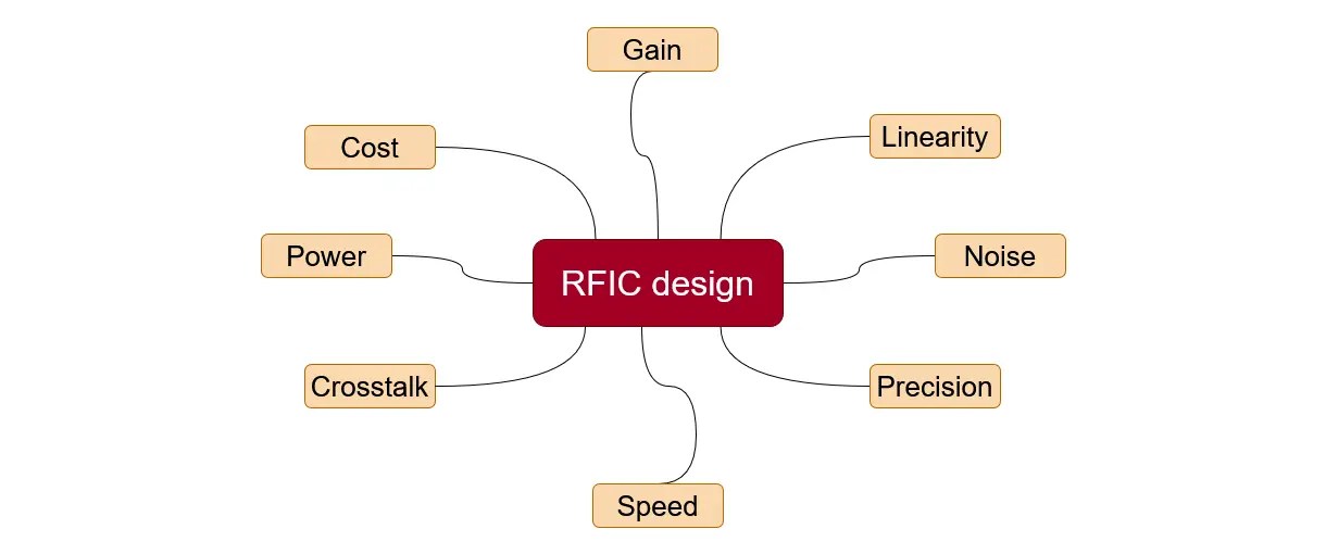
Fig. 1: RFIC design has to balance multiple objectives pulling in different directions.

Compared to digital ICs, RFICs are far more sensitive to noise, crosstalk, and parasitics due to high frequency and precision requirements. RFIC specifications impose far more stringent criteria on speed, power, gain, linearity, precision, power consumption, noise, costs, and radiated emissions.

While meeting customer demand for higher speeds, higher frequency bands, more features, and better performance, designers must delicately balance these often conflicting criteria.

The decisions and assumptions related to such balancing start from the schematic capture stage, the first step after the specifications and architectural decisions are made. Identifying all design problems and optimizing all tradeoffs at this early stage is far quicker and cheaper than doing it later. This is why “shift left” has become so important in the semiconductor industry.

By running RF circuit simulations directly against the schematics, designers can quickly explore different choices and assumptions and easily modify designs to achieve optimal tradeoffs. Designers can iteratively:

  • vary the values of passive components (resistors, capacitors, and inductors)
  • experiment with the bias thresholds of active components like transistors
  • re-run the simulations quickly
  • identify new problems that crop up
  • address them by modifying the design or design parameters

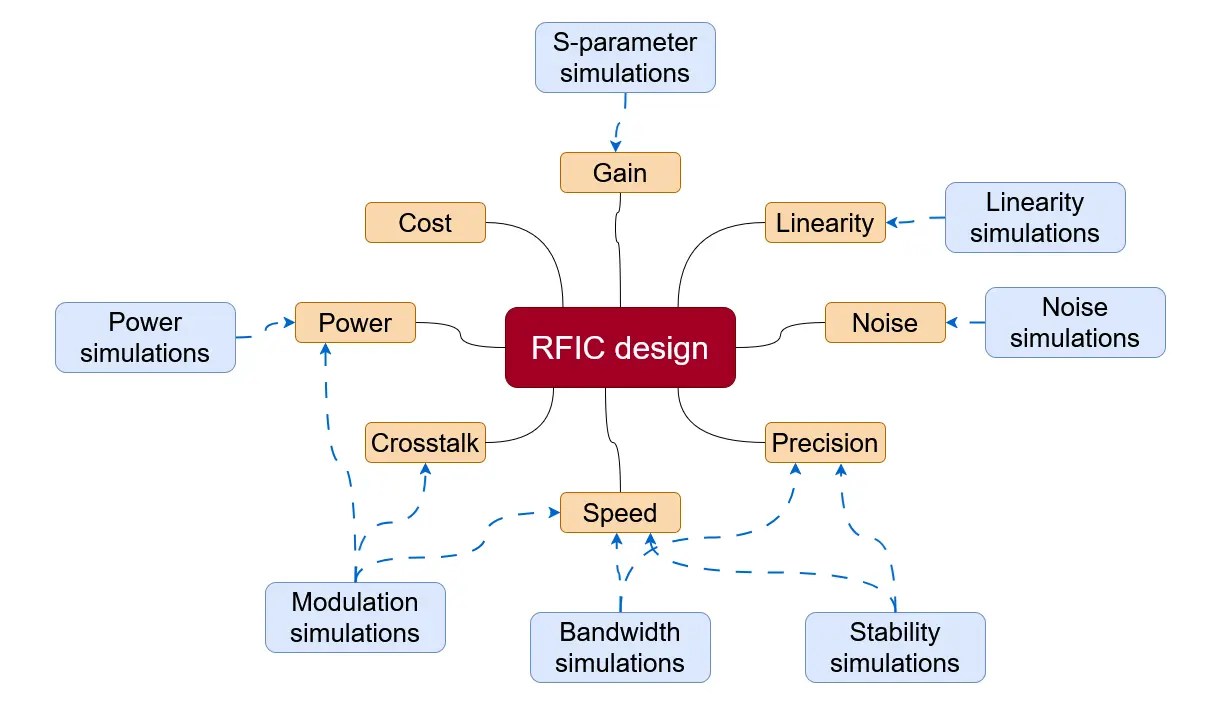
Fig. 2: Types of RF circuit simulations.

Some common RF circuit simulations are listed below:

  • S-parameter simulations: They enable designers to maximize forward gain (S21), minimize return losses (S11 and S22) for good impedance matching, and ensure high isolation (S12).
  • Linearity simulations: For RF power amplifiers and mixers, linearity simulations enable maximizing metrics like the one-decibel compression point and the third-order intercept point (IP3).
  • Noise simulations: For low-noise amplifiers and other sensitive receivers, these simulations help to minimize the noise figure.
  • Power simulations: For power amplifiers, simulations help to maximize the power-added efficiency or overall efficiency while minimizing power consumption in various blocks.
  • Stability simulations: Designers can verify unconditional stability across a wide range of frequencies by simulating factors like the K-factor and stability circles.
  • Bandwidth simulations: Designers can verify operating bandwidths for various metrics, such as flat gain or low return loss, within a specific frequency range.
  • Modulation simulations: Designers can simulate the complex modulation schemes used in real-world 5G, 6G, Wi-Fi 7, and other signals to explore the impact on metrics such as the error vector magnitude and adjacent channel power ratio.

Why is RF circuit simulation important?

Simulations add significant business, productivity, and technical value throughout the development cycle.

Let’s see some of the key business and productivity benefits:

  • Accelerate time to market: RF simulation significantly reduces the need for costly design respins and boosts the chances of first-pass success. Every iteration stretches the design cycle by months, leading to missed market opportunities.
  • Reduce costs: Minimizing the number of hardware spins also reduces fabrication costs.
  • Reduce lab time: Simulation reduces expensive physical measurement setups like anechoic chambers and high-cost test antennas.
  • Mitigate project risks: Simulation avoids discovering undesired behaviors or instabilities too late in the cycle.

There are significant technical benefits as well:

  • Prototype comprehensively: Using simulations, engineers can explore designs by tweaking values and parameters quickly and cost-effectively without requiring fabrication rounds, thereby saving immense time and costs.
  • Optimize performance: Simulation can achieve specific performance characteristics perfectly and early. Simulations can predict the magnitude of the error vector (EVM), phase noise, gain, and efficiency, which are crucial for modern communication systems.
  • Verify faster: Metrics suited for simulations, such as the error vector magnitude, can speed up simulation time by 10 times. Accurate simulations bridge the verification gap between theoretical design and actual performance.
  • Focus on higher-order effects: With a solid base design from simulation, engineers can focus on resolving more subtle, higher-order effects.
  • Prevent undesired behaviors: Simulation can identify issues such as circuit oscillations under varying load conditions, which are difficult to diagnose and correct in hardware.
  • Identify sensitivities: Simulation identifies what is sensitive and must be prioritized.
  • Facilitate innovation: Simulation enables the exploration of new architectures and materials without the prohibitive cost of physical experimentation.

What improvements are needed in next-generation circuit simulation software?

Existing simulation engines can do with some improvements in features and usability. We outline some of them below:

  • Improve user experience: There’s a need for intuitive user interfaces that enable cohesive, saveable, shareable, and reusable simulation and optimization workflows.
  • Decouple simulation setup: Remove the need for adding simulation setup to schematics to declutter them and improve reusability and transparency. Earlier tools inserted simulator controllers, probes, and other information directly onto schematics, making them messy and requiring removal for layout-versus-schematic verification.
  • Enable seamless interoperability: Integration across different electronic design automation (EDA) platforms is crucial for 3DHI modules that contain components from various design flows. Teams like RFIC, analog, and PCB currently work in isolation with disparate tools, data formats, and workflows, leading to fragmentation, collaboration challenges, and a higher risk of errors. Simulators must support standards like OpenAccess for EDA data.
  • Handle increasing complexity: The increase in complexity, speeds, and density requires more capable simulators and optimizers. Modern RF systems involve highly integrated systems-on-chip, MMICs, and advanced packaging solutions like 3DHI. RF simulation, particularly multi-physics simulation tools, must analyze the intricate interdependencies between thermal, electrical, and mechanical aspects in these complex structures.
  • Support 3D visualizations: Smith tubes, which are 3D representations of Smith charts, enable engineers to visualize component impedances across frequencies in 3D, facilitating the design of resonances that are not apparent in 2D.
  • Support faster metrics: Techniques like distortion EVM enable the rapid calculation of EVM without full demodulation, significantly reducing simulation time.
  • Analyze stability: Techniques that can account for complex high-frequency and load conditions and quantify stability margins are essential.
  • Simulate complex waveforms: Accurate simulation of complex waveforms, like 5G/6G signals, and their effects on metrics are needed, including the ability to integrate virtual test benches.
  • Provide more control: Existing simulator engines don’t provide much programmatic control or customization. Low-code solutions for better control are needed, especially for new designers.

How can innovations in RF circuit optimization reduce simulation time?

We said RFIC designs must balance many stringent and conflicting criteria. Simulators help with that by using optimizers. Optimizers are algorithms that automatically explore the vast design space of a schematic’s modifiable parameters, ensuring that all criteria are satisfied optimally.

However, current optimizers have some drawbacks:

  • Slow and inefficient: Some optimizers are slow, fail to efficiently converge for complex designs with many variables, or get trapped in local minima while searching for a global optimal solution. Traditional optimizers don’t fully exploit available parallel computing resources.
  • Poor support for complex signals: Classical IP3 tests and continuous wave signals don’t accurately model all aspects of complex 5G/6G signals, leading to large approximations and overdesign.
  • Poor integration: Integrating optimization workflows across different EDA platforms is time-consuming due to incompatible data formats and a lack of shared databases.
  • Lack of customization: Older platforms don’t support integration with machine learning (ML) frameworks or Python automation. Integrating external or custom optimizers requires months of joint customization work.

These drawbacks are overcome by modern circuit optimization implementations.

First, new algorithms like particle swarm optimization can handle challenging designs with large-scale variable counts and converge on multiple performance goals with up to 30x speed-up over traditional techniques. These algorithms also avoid local minima traps.

Second, multi-dimensional sweeps and sequences can be saved as workflows to ensure that all required performance specifications are consistently analyzed without requiring repeated configuration.

Third, real-time visualization of the optimization enables teams to quickly determine if an algorithm is effective or needs modification, thereby avoiding wasted simulation time.

Finally, these algorithms support headless operation for batch simulations and deployment on high-performance computing (HPC) machines, resulting in significant speed-ups.

How to solve your RFIC design challenges

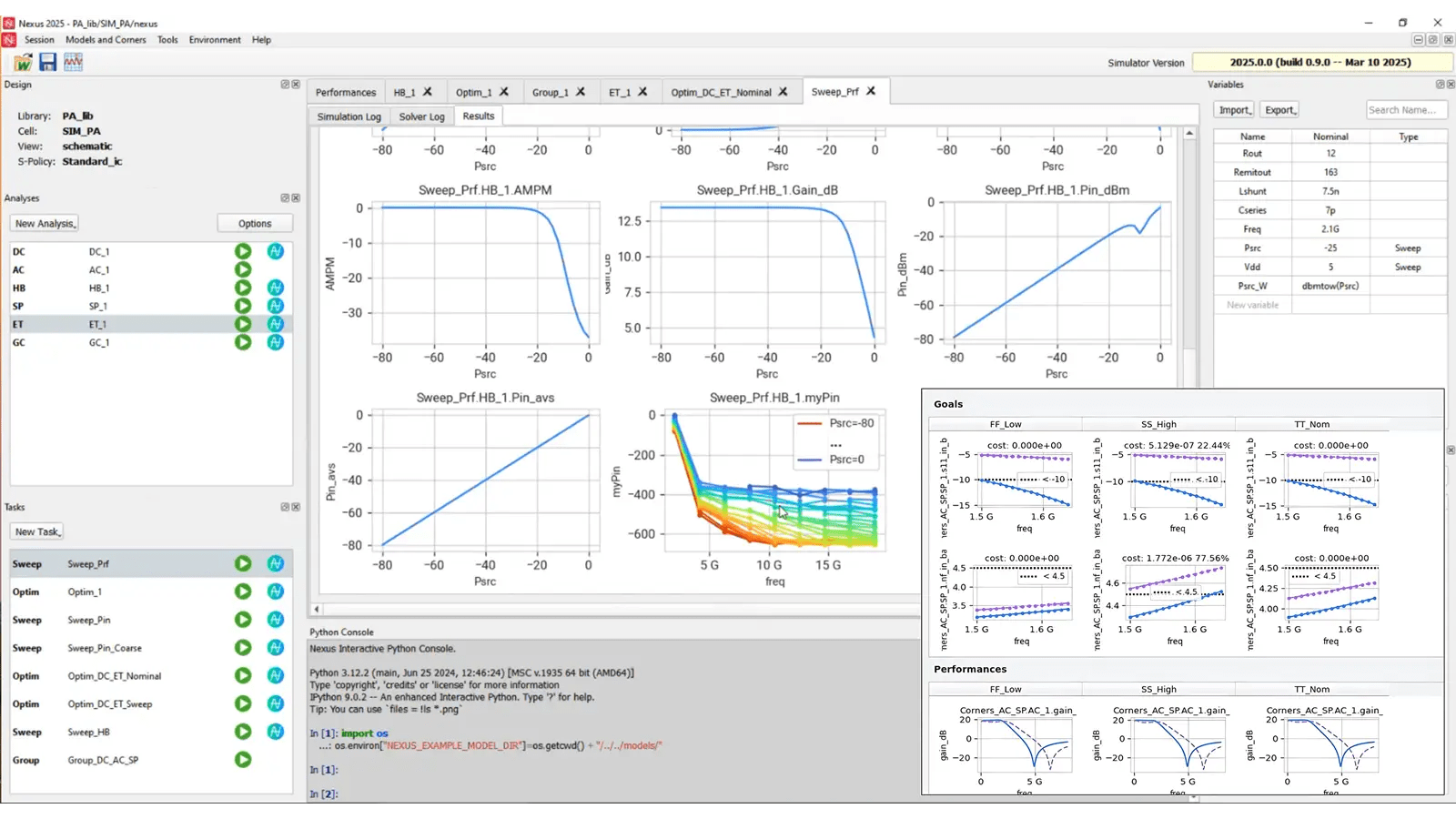
Fig. 3: Keysight RF Circuit Pro.

Keysight RF Circuit Pro revamps RF circuit simulation with several technical, performance, and usability improvements.

Integrated workflows

A unified, workflow-based user interface efficiently orchestrates simulation and optimization tasks. Setups are saved and reusable across design teams and EDA platforms, facilitating quick and repetitive analysis without the need for repeated configuration.

RF Circuit Pro works identically and integrates natively with all the industry-leading EDA platforms, enabling collaboration and reuse across diverse design teams and toolchains.

Multi-domain simulations can be configured with multi-dimensional sweeps, sequenced, and saved as workflows to ensure that all required performance specifications are consistently analyzed.

Multi-domain simulation algorithms

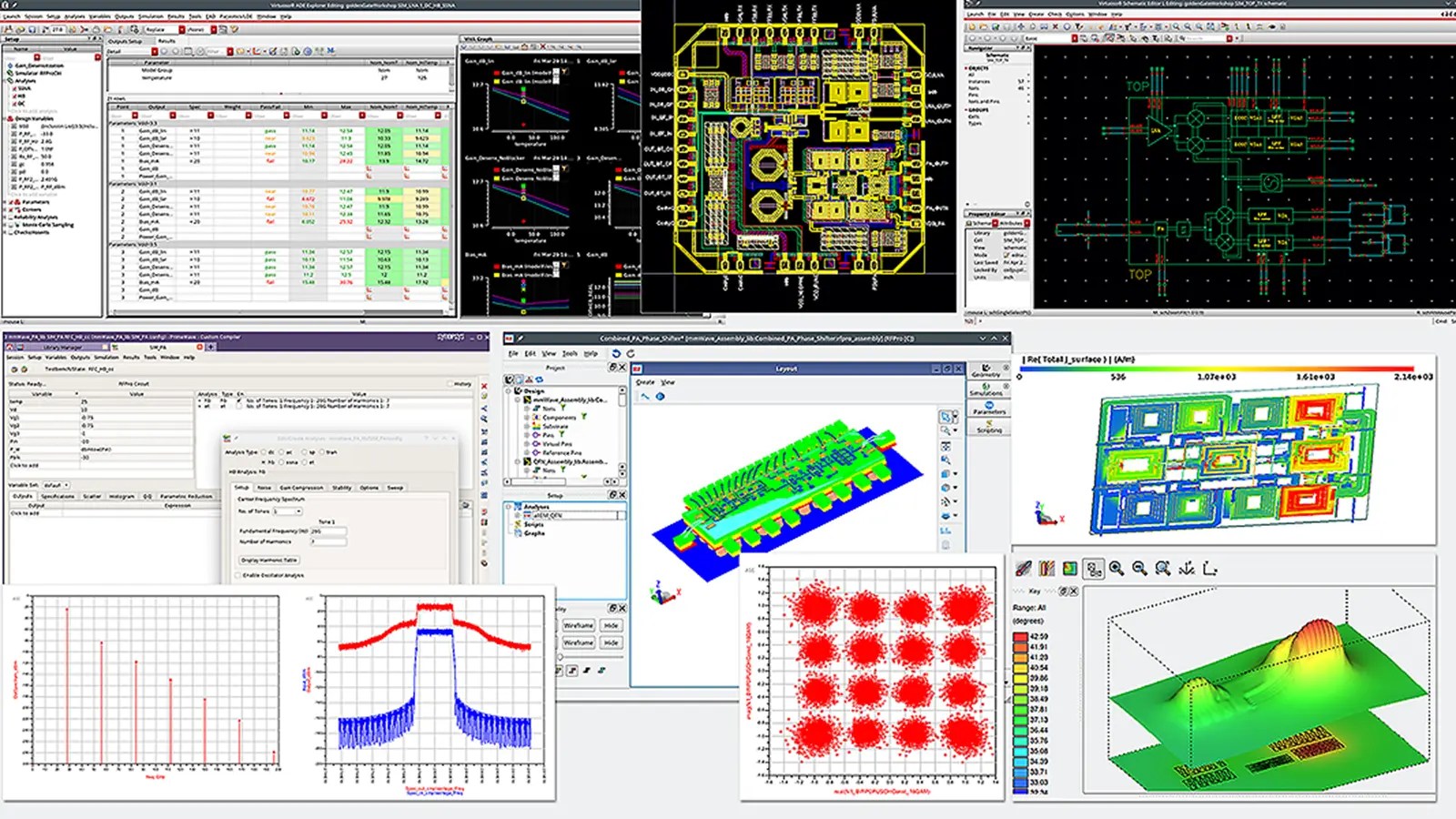
Fig. 4: RF Circuit Pro simulation, optimization, and visualization are consistent across Keysight ADS and other EDA platforms.

RF Circuit Pro includes a comprehensive suite of simulation algorithms like frequency, time, envelope, linear, nonlinear, stability, electro-thermal, system, and measurement. Together, they assist in multi-objective optimization of efficiency, EVM, adjacent channel leakage ratio, stability, gain, power supply output, 5G/6G compliance, and more.

Modern optimization algorithms, such as particle swarm and simulated annealing, achieve significant algorithmic speed-ups (of up to 30x) and avoid local minima traps, even for large-scale, multi-objective designs.

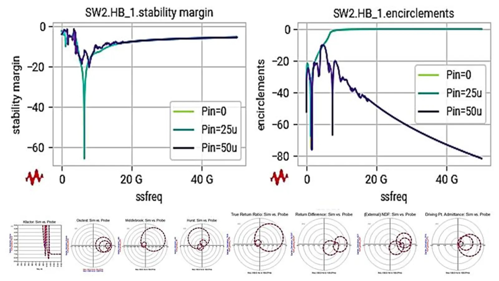
Fig. 5: Stability margin analysis estimates the amount of instability risk.

Advanced techniques, like Winslow probes and stability margin computations, can detect and quantify the stability of a circuit, helping designers avoid difficult-to-debug issues like oscillations.

Separation of analysis and tasks

RF Circuit Pro separates simulation analyses (like S-parameters and envelope) and tasks (like sweeps or optimization) for more efficient parallelization and significant speed-ups.

Parallel computing acceleration

RF Circuit Pro exploits parallel computing resources like local machines or HPC clusters for substantial speed-up (up to 16x) in both simulation and optimization.

Python automation and AI integration

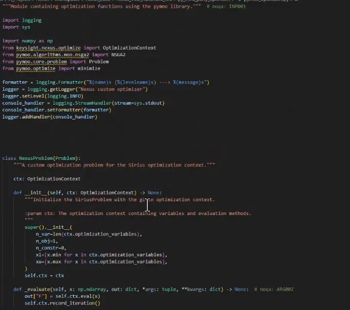
Fig. 6: Custom Python optimizer for Nexus.

RF Circuit Pro supports deep programmatic control and workflow automation by exposing comprehensive Python application programming interfaces (APIs).

RF Circuit Pro also seamlessly supports the integration of artificial intelligence (AI) and machine learning (ML) models into the simulation and optimization workflow. Designers can utilize neural networks, large language models (LLMs), copilots, and AI agents to enhance productivity and intelligent design.

3D heterogeneous integration

RF Circuit Pro supports the simulation of 3DHI aspects, enabling the combination of RFICs, advanced packaging techniques, and off-chip integration with printed circuit boards.

The common Open Access (OA) database enables RFICs designed in Virtuoso or Custom Compiler to be optimized together with off-chip packaging or in 3DHI modules using Nexus.

How does Python integration enable AI-assisted RF designs?

Nexus APIs support the integration of AI and ML algorithms for AI-assisted designs. Designers can integrate specialized ML models like neural networks, LLMs, or AI agents in their simulation and optimization workflows.

External Python-based optimization algorithms (like Pymoo functions) or custom commercial algorithms can be invoked to supplement the already powerful native optimizers.

Functionalizing physical designs via APIs enables massive simulation data collection to pretrain surrogate AI models. These models can then derive full sets of simulation data from extremely sparse data, thus reducing the number of required data points by a factor of 1,500 as well as the time required for the design process.

Get deep design insights with RF circuit simulations

In this blog, we demonstrated how simulations can help designers understand and predict the behavior of RF circuit designs at the schematic stage. Keysight RF Circuit Pro enables such deep understanding through efficient workflows and optimization algorithms.


Leave a Reply


(Note: This name will be displayed publicly)