Key mechanisms for test and fault isolation in PCIe lanes and links.

The PCIe specification has given a specific Link Training and Status State Machine (LTSSM) state named Loopback, which is intended for test and fault isolation use.
Basically, it gives a mechanism that involves looping back the data that was received in the Loopback LTSSM state. The entry and exit behavior are specified, and all other details are implementation-specific. Loopback can operate on either a per-lane or configured Link basis.
The PCIe 6.0 specification has improvised terminologies as follows:
As per the PCIe 6.0 spec, the Loopback Follower device enters Loopback whenever two consecutive TS1 Ordered Sets are received with the Loopback bit set.
The loopback bit is encoded as follows based on the encoding:

Fig. 1: Loopback LTSSM state.

Fig. 2: Training control Encodings for loopback in TS Ordered Sets for 1b/1b encoding.
PIPE6.0 defines a new feature called Digital Near-End Loopback (DNELB), which facilitates HVM testing by toggling signals via functional testing in Loopback mode. It introduces paths for looping back data like LB0, LB1, LB2, LB3, LB4, and LB5 for the PIPE interface and LB0, LB3, LB4, and LB5 for the SerDes interface. Based on the path selected by the controller or MAC, the PHY would undergo training in NELB mode.
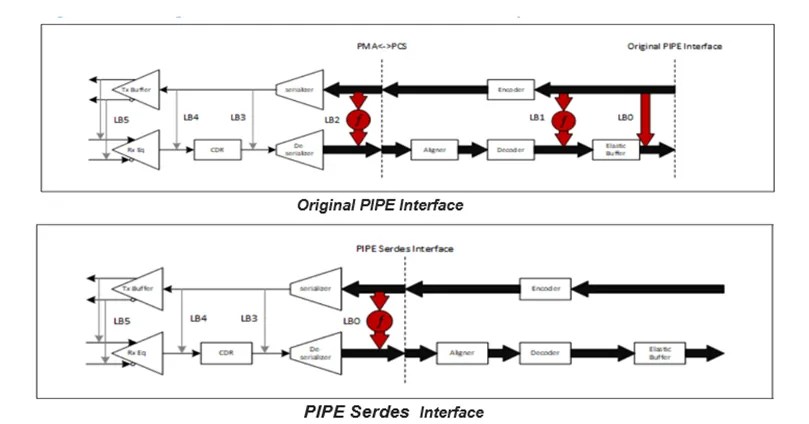
Fig. 3: Loopback Paths for DNELB.
Once the LTSSM state is negotiated to enter the Loopback LTSSM state, the MAC would write on the PHY NELB control register with the desired position and enable the set. Then, upon receiving the desired acknowledgment, the MAC becomes free to train the NELB.

Fig. 4: PHY Near-End Loopback Control Register.

Fig. 5: Near-End Loopback Status Register.
The exit from the NELB is done when the MAC clears the enabled bit from the PHY NELB control register, and once the desired acknowledgment is received, the MAC becomes free to do normal operation.
More information
 |
|
 |
 |
 |
 |
Leave a Reply