As line/space measurements fall below 50nm, shape-based MDP and MV are no longer sufficient.

Since the beginning of the semiconductor industry, mask-data preparation (MDP) and mask verification (MV) have been shape-based: each shape has been treated as an entity unto itself, and if each isolated shape was correct, the mask was correct. This context independence is a critical assumption for conventional fracturing.
However, as line/space measurements (L:S) fall below 50nm, shape-based MDP and MV are no longer sufficient. With L:S below 50nm, the ability of each individual shape to print faithfully on the mask is impacted by its proximity to other shapes. The context for each shape on the mask becomes as important as the shape itself. The solution is to create and evaluate each shape within the context of its surroundings. This is why below 50-nm L:S, simulation-based MDP and MV methodologies become critical.
To demonstrate the impact of context below 50nm, consider the example in Figure 1 below. The basic layout is 10 alternating lines and spaces, with a large area of 100% exposure to the left and a large area of no exposure to the right. Figure 2 shows a 1000-epoch Monte Carlo simulation of this pattern. At 300-nm L:S, this pattern is an example of “what you see is what you get,” and it reproduces with reasonable faithfulness down to 50nm. However, at 40-nm L:S, there is significant line-end rounding and shortening. Further, the lines on the left (lines 1-2) vary quite a bit from the lines on the right (lines 9-10).
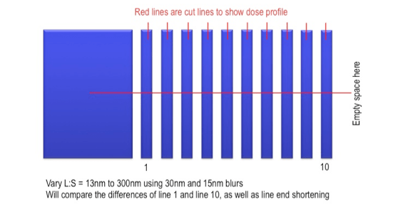
Figure 1: The test pattern used for simulation. It is a simple L:S pattern with 100% exposure to the left and 0% exposure to the right.

Figure 2: Simulated mask contours for combined blur of 30nm are shown for various L:S patterns. This would be the result of printing for conventional fracturing with no short-range correction. Each picture is scaled up to enable the reader to see the contours. In reality, 100nm L:S pattern is a third the size of the 300nm L:S.
These differences are troublesome, not because the lines cannot be corrected, but because they cannot all be corrected in the same way. Dose modulation is one very effective way to correct line-end rounding and shortening. However, if the same corrective dose was applied to every one of the lines, the right-most lines would be over-corrected, and the left-most lines would be under-corrected. This is where rule-based MDP and MV begin to encounter trouble. While it is theoretically possible to create rules complex enough to deal with context-based issues, in practice, the resulting rules base would be both byzantine and inaccurate.
The mask-making world, of course, has another solution for writing finer geometries on the mask reliably. Slower resists with less blur write finer geometries more accurately. The required increase in energy can be supplied by a higher current density or a longer write time for a VSB machine, or with a multi-beam mask writer, which is designed for higher current densities. The simulations in Figure 3 show that slower resists do help: at 15-nm combined blur, the lines in this example would print fairly well down to 40-nm L:S. However, the context-dependent effects do appear at 30nm and below. Context-sensitivity calls for a simulation-based MDP methodology.

Figure 3: Comparison of the simulated contours for 30nm, 40nm, and 50nm L:S patterns for 15nm blur on the right vs. 30nm blur on the left.
The costs of adopting a simulation-based MDP methodology are runtime and model development. However, simulation-based MDP offers several well-established benefits that come from enabling techniques, including overlapping shots, dose modulation of individual shots, and model-based shape modulation. These techniques not only help to achieve linearity correction, but also help significantly to improve resilience to manufacturing variation. The runtime costs associated with a simulation-based MDP methodology can be significantly reduced by using GPGPU-acceleration, which works particularly well for eBeam simulation.
Figure 4 shows the results of a simulation-based, context-sensitive dose modulation and shape-correction performed on the bottom set of patterns. Only line widths are corrected in this study, not the line-ends. Because the corrections are simulation based, and thus context-sensitive, each line is adjusted differently each time, taking into account the surrounding environment.

Figure 4: 15nm blur process is simulated to make dose-based corrections with each line edge being treated specifically in its context by simulation. Only line widths are treated in this study; line-ends are not corrected.
It is clear from these simulation examples that for features or jogs below 50nm (or below 40nm with a combined 15-nm blur), mask shapes are predictably different by more than 2nm depending on the context of the neighboring shapes. Context sensitivity requires simulation-based processing because rule-based, geometric approaches are too complex to generate the accuracy required.
Simulation-based MDP is ready today for the 50-nm challenge while the industry continues to work on alternative lithography solutions. The eBeam community continues to innovate to fill the gap and enable extensions to optical lithography. Simulation-based MDP, combined with GPGPU acceleration, delivers the performance and context-sensitive precision to extend optical lithography to the 10-nm logic node.
 |
|
 |
|
 |
 |
 | |
 |
 |
Leave a Reply