Using computational fluid dynamics to design and select the ideal heatsink.

By Yousaf Mohammed, Student Intern at Mentor Graphics
When designing electronics, heat dissipated to the surroundings by micro devices is an important consideration because heat has a powerful and stringent effect on their operation and lifespan. When an electronic device overheats, components start to wear out more quickly, degrade, cross the threshold into safe mode, and then stop functioning. The consequences can eventually cause premature failure to the whole system. Therefore, as these technologies continue to develop, thermal management plays an influential role in the functionality and performance of today’s electronic devices.
So, how do we manage this thermal issue in electronic devices? The three main methods of transferring heat from one place to another that we have been taught are convection, conduction, and radiation. The method of convection is when heat is transferred from a solid surface to its surrounding fluid. Conduction is when heat is transferred through a solid material. In conduction, the choice of material is important because materials that are good conductors, such as copper and aluminium, are mostly used for rapid heat transfer in electronic devices. Lastly, radiation in electronic devices is the electromagnetic radiation caused by temperature. The intensity of heat transfer through radiation is far less effective compared to conduction and convection.

Figure 1: Typical heat transfer around a heatsink.
So, how do we eliminate the unwanted heat that is given out by these electronic devices? Many techniques can be used for cooling, but the most effective are heatsinks. Heatsinks are the big metal objects in electronics systems such as the CPUs, graphic cards, etc. The efficiency of the heatsink greatly depends on the construction of its design. Some factors need to be considered to maximize the efficiency of a heatsink. The most significant consideration is the power dissipation that needs to be removed by the heatsink. The second consideration is the nature of the flow, that is, the amount of fluid flow and any bypass in the heatsink. The third consideration is the magnitude of the pressure drop in the system upon introducing a heatsink. The last consideration is the design, including the cost of the design and whether it can actually be manufactured, as well as the right materials to be used. Copper has around twice the thermal conductivity of aluminium, but it is three-times denser than aluminium so it should only be used when necessary.
The best method for cooling electronic devices is to integrate heatsinks into the source’s surface by increasing the surface area. Heatsinks enable a more efficient heat transfer from the heat source to the adjacent fluid by using the extended surface area. Heat is transferred from the source to the heatsink by conduction; it is then transferred from the heatsink to the surrounding fluid by convection and can also be transferred to the surrounding area by radiation.
These devices that are mostly used in every electronic system give out huge chunks of unwanted heat. In other words, heatsinks are passive heat exchangers, which work by absorbing heat from the source and diffusing it into the air by combining it with a fan or a rotating device to actively cool the system’s components. Diffusion of the heat normalizes the system’s temperature and prevents it from overheating. Speaking of increased surface area and taking up chunks of space, adding a fan directly into a heatsink can be an inexpensive and space-efficient means of intensely improving heatsink performance by forced convection.
How do we go about designing and selecting a heatsink that is fit for this purpose? Also, what are all the known factors that can increase the efficiency of the heatsink? How do we design and optimize a heatsink that would provide an acceptable temperature with maximum efficiency and minimum cost? The answer is to use computational fluid dynamics (CFD). CFD uses numerical nonlinear differential equations that describe fluid flows (Navier-Stokes equations) for fixed geometries and boundary conditions.
The main advantage of CFD is that its virtual modelling methods with powerful visualization capabilities can be used to estimate the performance of a wide range of applications. CFD predicts the performance of a system without modifying the actual system or the prototype. Therefore, CFD predicts which design changes are most essential to enhance the performance without having to even touch the actual prototype. CFD provides exact or even better and detailed information about the system than any other theoretical or experimental methods. CFD also costs much less and is less time-consuming than carrying out experiments because it does not involve physical modification of the system.
During my internship, I used the CFD simulation package FLOTHERM XT V3.0 by Mentor Graphics to measure the performance of two different heatsinks on a printed circuit-board (PCB). The PCB is homogeneous with isotropic thermal properties. These properties are often used in PCBs with many layers of resistant material with copper traces along the board. This gives the PCB thermal resistivity along the circuit-board rather than through it. The total power of the main chip was 1 W, elongated chips around the main chip were powered at 2 mW, and the mini chip on the right was powered at 1 mW on the PCB.

Figure 2: PCB with different layers and traces of copper.
I ran the first simulation with only the PCB to estimate the total power dissipation. The temperature of the main chip was measured to be at 55.7 oC. The results showed that the heat diffusion and the heat loss through natural convection was not enough to cool the main chip on the PCB.

Figure 3: The temperature distribution of the PCB.
In the second simulation, I added a rectangular, inline heatsink directly onto the top of the main chip with a thermal interface layer between them. I used the thermal interface layer of aluminium nitrate, which is highly recommended because of the dry air gaps that provide a thermal resistance between the main chip and the heatsink.

Figure 4: Conduction through thermal interface material filling dry air gaps.
A thermal interface material (TIM) is necessary when two or more solid surfaces are attached in a heat path in electronic devices. Typical machined materials have rough and wavy surfaces with fairly few actual contact points between surfaces. The gaps between the two surfaces are filled with air that acts as an insulator and as a barrier for the heat transfer between the two surfaces. Therefore, using the TIM by filling the voids and eliminating the air between the two surfaces improves the process of conduction and enhances the heat transfer between the two materials.

Figure 5: Rectangular, inline heatsink pin geometry information.
Some simple hand calculations need to be done to find the most suitable heatsink for any application, first using correlations, then using the fin-efficiency formula. The typical correlations calculate the heat-transfer coefficient for flow over a flat plate. They are extensively available in engineering heat-transfer text books. The more fins the better for the heat exchange at the surface, but with an increased number of fins, the heat-sink pressure drop also increases. Therefore, there is an optimum number of fins for a given flow rate.
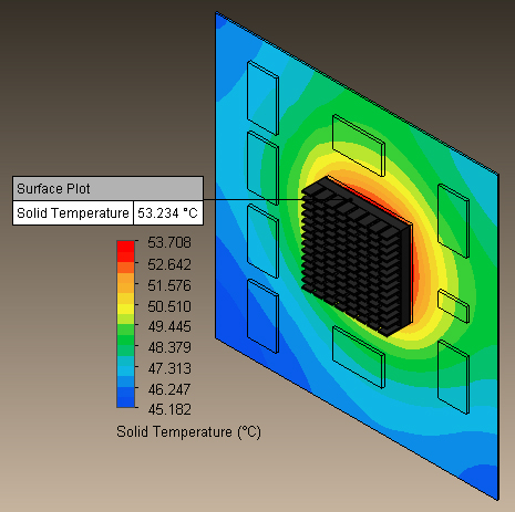
Figure 6: Rectangular, inline heatsink attached directly to the top of the main chip on the PCB.
In the second simulation, I attached the heatsink directly to the top surface of the main chip with the TIM. I chose aluminum for the heatsink. The results from the simulation showed that the temperature of the main chip decreased by the addition of the heatsink with natural convection. The temperature dropped from 55.7 oC to 53.2 oC, with a decrease of 2.5 oC in the total temperature of the main chip.

Figure 7: Rectangular, inline heatsink with an attached transparent fan.
In the third simulation, I attached a fan directly onto the top surface of the heatsink fins with a flow rate of 0.008 m3/s directly blowing into the heatsink. The temperature of the main chip reduced by an exceptional amount to 36.3 oC, with a temperature difference of 19.4 oC by forced convection when I added the fan from the FLOTHERM XT V3.0 smart part library.

Figure 8: Radial self-rotating heatsink.
In the last simulation, I used a self-rotating heatsink combined with a heatsink and a fan. The rate of spinning was adjusted to 100 RPM, sitting on top of the main chip with the interface layer in-between. I applied the rotating region boundary condition to the heatsink from the CFD library to achieve the spinning. This type of heatsink is known to be very efficient because it removes the thermal resistance by cutting the amount of stationary air caused by the spinning of the heatsink and moving parts around the main chip.
When the self-rotating heatsink was attached onto the top of the main chip, the temperature reduced to 35.7 oC, with a temperature difference of 20.0 oC. The rotating region smart part that I used from the CFD library helped to achieve this outstanding performance.

Figure 9: Cylindrical self-rotating heatsink.
In conclusion, comparing all the CFD simulations that I conducted, the self-rotating heatsink was highly efficient in removing the heat generating by reducing it to 35.7 oC from 55.7 oC, a difference of 20.0 oC. The self-rotating heatsink is also known to be really quiet, and it occupies less space than any other heatsink.
References
http://www.engscope.com/pcb-fab-tutorial/02-pcb-basics/
http://www.electronics-cooling.com/2003/11/thermal-interface-materials/
 |
|
 |
 |
 |
 |
Great work on ‘What I Learned About Heatsinks Using Thermal Simulation’, Mohammad. May I repost this? Of course I will give you credit.