Correct specification of FPs and MCPs is critical for proper synthesis results.

Designing with synchronous clocks avoids metastability issues on clock domain crossings, but it presents its own challenges when multi-cycle and false paths are involved. A multi-cycle path (MCP) occurs when a logical function requires more than one clock cycle to produce a final, stable result. The designer must ensure that the destination register does not clock until the result is ready. This typically requires an enable that does not activate until the required number of cycles have elapsed after a new value is loaded into the source register. The designer must also ensure that the logic synthesis tool does not waste time trying to cram the MCP function into a single cycle and that static timing analysis delivers accurate results.
A false path (FP) occurs when there is a physical path through the logic that will never be enabled during actual usage. The designer must ensure that logic synthesis and static timing analysis ignore false paths. An FP will never be exercised, so synthesis must not attempt to fix races on short paths or optimize long paths. Doing so would consume compute resources and add unnecessary logic to the design. The designer needs a simple, effective, and consistent way to communicate MCPs and FPs to all relevant tools in the design and verification flow so that the results are correct.
A recent blog post discussed the use of Synopsys Design Constraints (SDCs) for exactly this purpose. SDCs can specify clocks, timing, setup and hold checks, MCPs, FPs and other useful information in a single file to guide logic synthesis, static timing analysis and other steps in the development flow. The SDC syntax is straightforward and natural for the designer. For example, the constraint “set_false_path -through signal1 -through signal2” defines any path including the two specified signals as false. Any path meeting this constraint should be ignored during analysis or synthesis.
For tools to provide correct results, the SDCs provided to them must be accurate. The previous post discussed several ways to verify the constraints. The project’s register transfer level (RTL) linting solution must have SDC capabilities, so it can flag typographical errors, missing information, and references to signals and modules that are not found in the register RTL design. It is run early in the development flow, so the designer does not have to wait until logic synthesis to find SDC issues. The linting process must also generate MCP and FP properties and verify them with formal engines. If it cannot obtain a definitive formal result for some properties, it should export them to run in RTL simulation.
This approach catches additional SDC errors, but it cannot find them all due to the nature of traditional RTL simulation. Consider the MCP example of a two-cycle multiplier, specified by the “set_multicycle_path 2 -setup -from ff1* -to ff2*” constraint. The multiplication result register must not clock until the product has been computed. If the result register clocks every cycle, it will load incomplete and incorrect data for the first cycle of every two-cycle multiplication. Adding an enable to the result register ensures that it does not load a product until two cycles after new values have been loaded into the multiplicand and multiplier registers.
If the designer forgets to add the enable, this bug will not be detected in traditional RTL simulation. Since multiplication results are available instantly, every product value loaded will be correct. With full-timing gate-level simulation (GLS), the final product is not available until two cycles have elapsed, so the result is incorrect. Historically, this has been the only way to detect some types of MCP and FP bugs. However, GLS runs much slower than RTL simulation and failures are much harder to debug. In addition, GLS happens late in the project, when fixing every bug takes significant effort and delays tape-out. A better way is needed to “shift left” the detection and resolution of MCP and FP issues to reduce verification time and effort.
The solution is to use an RTL simulator with the capability to read in the SDC file directly and take constraints into account. SDC-aware simulation either triggers an assertion violation or injects X (unknown) values when a multi-cycle result is loaded prematurely. If an assertion is triggered, it points to the specific MCP where a value was prematurely loaded into a result register. If the result register loads data prematurely, X-injection ensures that an unknown value is loaded. If this value is propagated to an observable failure point relying on the multiplication result, the bug is detected. The screenshots below show how this looks to the designer or verification engineer debugging the failure.
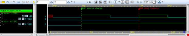
Regular RTL simulation of the buggy MCP design.
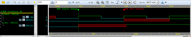
SDC-aware RTL simulation of the buggy MCP design.
This approach is also used to verify FPs. An FP can be specified in SDC as an MCP with an arbitrarily large delay, perhaps 100 clock cycles. If the value propagated through a FP is loaded into the result register at any point before this large delay, an assertion violation is reported, or an X is injected.
Correct specification of FPs and MCPs is critical for proper synthesis results on complex chip designs. The Synopsys VCS simulator supports the unique approach of SDC-aware RTL simulation and the Synopsys SpyGlass Constraints solution includes extensive SDC linting capabilities. Together they provide high confidence in the correctness of SDCs early in the project timeline. This significant shift left in MCP and FP verification is also faster and easier to use than GLS with back-annotated timing. This novel approach is essential for today’s complex chips.
A white paper with more details is available.
 |
|
 |
 |
 |
 |
Leave a Reply