There are still some problems to work out, such as cutting defect rates, but directed self-assembly has the potential to reduce the total number of masks.

The upcoming 7nm process node presents tough challenges both for printability and cost. At 7nm and below, multi-patterning is required, which makes the manufacturing process more expensive by requiring more masks. To control costs, any alternative technology that provides equivalent yields with fewer patterning steps should be explored.
One promising option is to use directed self-assembly (DSA) of block co-polymers to create contacts/vias. DSA for contacts/vias shows low defectivity rates while being able to shrink the dimensions of the intended target. DSA can also be applied to metal cut. Perhaps more importantly, it reduces the number of masks needed.
There are two basic DSA approaches with block co-polymers: grapho-epitaxy and chemo-epitaxy. In the past few years, there has been substantial progress in simulating and printing contact/via layers for 7 nm node with the grapho-epitaxy DSA approach, so that is the approach we’ll discuss here.
With the DSA grapho-epitaxy approach, a block co-polymer is added between guiding templates with topological geometries. To form contacts/vias with the block co-polymer, the guides physically confine the block co-polymer material (polystyrene-block-poly-methyl-methacrylate, or PS-b-PMMA) to induce the formation of single or multiple uniform contact holes to the target points, with sizes (d in Figure 1) and pitches (s in Figure 1) being well below the optical resolution limit. The spacing of the guides determines the pattern that the block co-polymers form.

Figure 1. The grapho-epitaxy DSA approach. Courtesy Professor Wong’s group from Stanford.
The DSA cylinders’ formation varies with different guiding pattern confinements. Figure 2 shows Monte Carlo simulation results with rectangular guiding templates. The DSA material composition is 60% block co-polymer and 40% homo-polymer. The width of guiding rectangle bars is 40nm, and the length (CD^Y in the figure) varies from 40 to 200nm in increments of 10nm. The red contours represent the guiding patterns; pink, green, and blue contours show the simulated results of DSA cylinders on the top, middle, and bottom planes along the Z direction of the guiding pattern.
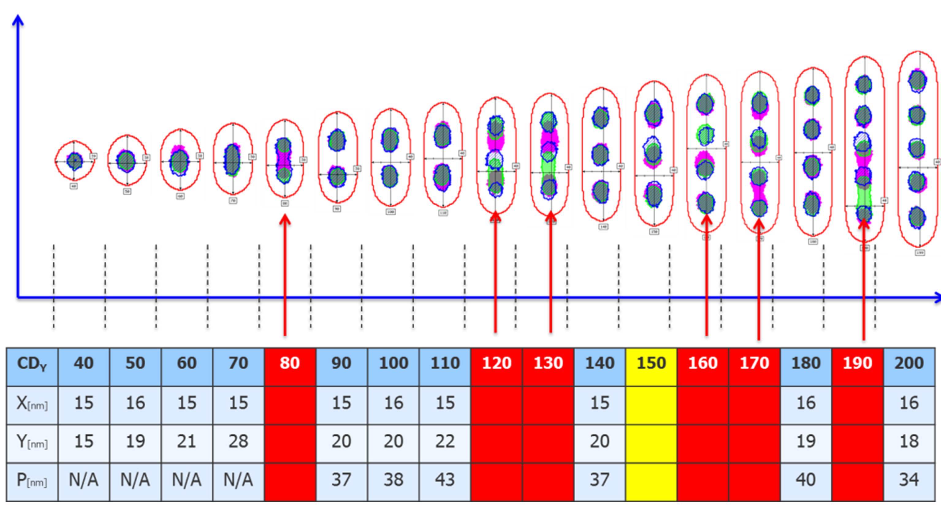
Figure 2. The DSA patterning. Guiding patterns determine the number of cylinders formed. Red blocks in the table identify phase transitions.
In this example, the pink contour represents the shape at the top of the cylinder, and the blue is the shape at the bottom of the cylinder. The natural pitch of this material is about 37+/-3 nm, and the natural size of the cylinders is about 15nm X 15nm. The longer the guide length, the more DSA holes are formed. However, there are phase transition regions where the number of DSA-formed holes increases from N to N+1 as template length CD^Y increases. For example, the template size of 80nm shows a phase transition where the number of DSA-formed holes increases from one to two. However, unlike the single contact hole formed when CD^Y=40nm, the features formed at CD^Y=80nm are ill-formed, and do not make straight holes through the Z direction. When CD^Y=90nm, two clear DSA-formed holes appear. What becomes clear when looking at Figure 2 is that there are four CD^Y sizes (40, 50, 60 and 70nm) that can be used for single contact design, three (90, 100, and 110nm) for double contact design, two (140 and 150nm) for triple contact design, and one (180nm) for quadruple contact design. The design window for block co-polymer DSA narrows as the template lengthens to avoid these phase transition regions, which are labeled in the red blocks of the table.
As for the best guide shape, experiments suggest that “peanut-style” guiding patterns, which are rectangles that are pinched in at the waist, are better than true rectangles. Figure 3 shows SEM images of “peanut-style” guiding patterns with different degrees of modulation, and their corresponding DSA cylinders. The guiding templates in Figure 3 (a) are designed so that the modulation increases from the left to the right, and the number of DSA-formed holes increases from two to four from the top to the bottom row. Figure 3 (b) clearly shows better DSA cylinder formation with larger modulation for all designs.

Figure 3. Pitch multiplication of block co-polymer as resolution enhancement technology: (a) guiding patterns with modulation increasing from left to right, (b) the DSA formation using guiding patterns in (a).
DSA and the bottom line
The grapho-epitaxy DSA approach can reduce the need for one or two masks by grouping the neighboring sub-resolution contacts/vias together, and putting them on the same mask with guiding templates that are optimized for the block co-polymer material characteristics. Reducing the number of masks may greatly reduce the manufacturing cost, compared to the traditional multi-patterning technology.
To demonstrate a promising cost-effective flow with DSA technology, we’ll use an aggressive via layer design as an example. Figure 4 (a) shows the original design with minimum pitch of 42nm. The design has multiple sub-resolution pitches. Since the dimensions of the vias or the metal cuts are well below the resolution possible with 193i, the layer would need to be decomposed in multiple exposures. In this early prototype of the layout, the layer requires quadruple patterning to perform the pattern transfer with sufficiently robustness, as shown in Figure 4 (b) where different colors represent the different masks.

Figure 4. Original via layer and the required quadruple patterning coloring: (a) original intended design—given the dimensions of the minimum pitches for this 7 nm prototype layout, quadruple patterning is required, (b) a quadruple patterning decomposed layout shown in different colors.
The DSA process can pattern this layout in at least a one less patterning step, taking the layout from quadruple patterning to triple patterning, as shown in Figure 5.

Figure 5. From quadruple to triple patterning using DSA.
Once the data is separated, the full process of creating the guiding patterns for DSA can commence. The sub-resolution features are grouped for formation with peanut-style guiding patterns. Figure 6 shows the grouping and the guding pattern generation, the optical proximity correction (OPC), and the guiding pattern response for the DSA mask 2 target from Figure 5. These guiding patterns are then evaluated and proper cylinder formation can be confirmed.

Figure 6. Robust DSA printing.
Creating DSA contacts/vias requires a DSA-aware mask synthesis flow, as shown in Figure 7. The first step is a grouping function, which takes a design as input, and then groups features together if they are DSA design-compliant. Non-compliant DSA features are considered design rule violations, and must be redesigned. Next, the DSA synthesis function takes the resulting groups from the previous steps and generates DSA templates, which must be patterned onto the wafer. An OPC step is required to achieve the target templates and compose the necessary mask shapes.

Figure 7. The DSA-aware mask synthesis flow. Three functions are unique to DSA: grouping, synthesis, and DSA verification.
Because of lithographical process window variations, which will cause guiding pattern distortions, the generated mask must undergo a lithographic verification to guarantee the imaging quality and robustness of the guiding pattern shapes. Finally, the DSA verification needs to check if the guiding pattern images across multiple process windows result in robust formation of DSA cylinders. There are three operations unique to enabling a DSA process: DSA grouping, DSA template synthesis, and DSA verification. While grouping relies on DSA-aware design rules, DSA synthesis and DSA verification require DSA-specific models.
Conclusion
Before DSA is widely adopted, defect rates must be reduced, and placement error rates must be low enough to meet overlay requirements. DSA-compliant design and DSA-aware mask synthesis become necessary, because DSA grapho-epitaxy strongly depends on the confinement imposed by the guiding templates. These tools are largely in place or are being quickly developed.
Using DSA for technology nodes 7nm and below has the potential to reduce the number of masks needed by grouping neighboring sub-resolution features and placing them on the same mask. In addition, DSA can be used with existing optical technology to achieve both flexible designs and faithful patterning goals at the same time without increasing the cost.
In my next blog, we will show solutions for DSA using source-mask optimization (SMO) and pxOPC to achieve sub-80nm non-L^0 pitches for DSA patterns using 193i, and introduce an optimization methodology for the guiding pattern designs using the notion of Template Error Enhancement Factor (TEEF).
For details about this DSA work, download this related technical paper: Cost Effective Technology Scaling with Directed Self Assembly.
 |
|
 |
 |
 |
 |
Leave a Reply