First of two parts: Different schemes emerge for moving signals down channels more quickly.

Chip interconnect standards have received a lot of attention lately, with parallel versions proliferating for chiplets and serial versions moving to higher speeds. The lowliest characteristic of these interconnect schemes is the physical signaling format. Having been static at NRZ (non-return-to-zero) for decades, change is underway.
“Multiple approaches are likely to emerge,” said Brig Asay, director of strategic planning at Keysight Technologies. “It’s hard to say what will win.”
At the high-speed range where these connections operate, there are no multi-drop buses. Everything is a point-to-point connection. And the number of different standards and speeds is enormous. But what differentiates those standards, aside from their being parallel or serial, tends to be higher-level characteristics:
• Higher protocol layers
• Specific locations of signals on packages
• Voltages and slew rates
For all their higher-level differences, many share the same physical signaling. At that level, it doesn’t matter so much whether it’s a memory interface or PCIe. It’s all about how the signals move down the channel. That signaling, once rather prosaic, has gained the focus of high-powered engineers.
Bandwidth is determined by the clock rate, the number of lines in the channel, and the number of bits that can be transmitted on a line for a given clock rate. Looking at individual lines, there are at least four ways to speed up the signaling — dialing up the clock rate, reducing voltage swings, designing better circuits for higher fidelity, and introducing new signaling formats that pack more bits into each symbol. These tools are being used differently, depending on whether the connection is parallel or serial.
Regardless of whether a connection is serial or parallel, “even short reach is a transmission line,” said Manuel Mota, product marketing manager for high-speed SerDes PHY, analog, and Bluetooth IP at Synopsys. Termination and coupling must be handled properly to maintain signal quality.
Single-ended wires are a thing of the past. Any signal at this speed must use some form of differential signaling to eliminate common-mode noise. This makes the terms “wire” or “line” misleading. “Lane” is a more common way of referring to a set of wires carrying a single stream of data, but it often implies both sending and receiving directions in a single lane. For our purposes, we’ll use the term “channel” to describe a single signaling group going in one direction.
Serial connections
The serial interconnect has seen much of the recent action. Rather than running bits in parallel along separate channels, bits are serialized and run on a single channel. It’s possible to have multiple serial channels running next to each other, but each will be running its own serial stream. Mota said,
Others agree. “Anything going any distance will be serial,” said Amin Shokrollahi, CEO of Kandou. “For greater than 1mm, people don’t do parallel. Sometimes the signal is barely above the noise floor.”
Serial connections can be clocked over 100 GHz, and some folks are looking higher than that. “People are talking about 200GHz,” said Wendy Wu, director of marketing in the IP Group at Cadence. “But the use case for 200GHz isn’t clear yet.”
To eliminate clock/data skew, the clock isn’t forwarded to the receiver directly. Instead, it’s encoded onto the data stream and recovered in the receiver by a clock-data recovery (CDR) block. That CDR block contains phase-adjustment elements like phase-locked loops (PLL), which also can be used for de-skewing purposes.
For that PLL to maintain lock, it must see sufficient transitions to keep it running. A data stream having a long run of zeros would cause the PLL to lose lock. To avoid this, encoding schemes have been devised to ensure sufficient transition density. Because typical serial lines are AC coupled, these schemes also ensure that the number of 1s and 0s (so-called “disparity”) is balanced to ensure that the voltage on the lines remains centered.
The oldest and most common such encoding scheme is called 8B/10B, which codes 8 bits of raw data into 10 encoded bits. That’s two overhead bits for every 8 data bits, which is high if used for transmitting large blocks of data. So, more recently, a 64B/66B scheme was developed that has two overhead bits for each 64-bit segment. A 128B/130B encoding is used by PCIe 3.0, and USB 3.1 and DisplayPort 2.0 use a 128B/132B scheme, further reducing overhead.
By encoding clock and data together, they can travel long distances with no additional skew. The path traveled can include packages, connectors, and other mechanical elements in a way that the fastest parallel connections cannot.
The most recent changes to serial technology involve the signal format. “Right now, the state of the art in the market is PAM-4,” said Cadence’s Wu. Up through the 28GHz range, and even for some 56GHz channels, NRZ is still the preferred format. But for some 56GHz and all 112GHz channels, PAM-4 has been adopted relatively widely.
“50 GHz is the transition above which PAM-4 was accepted,” Wu noted. “It took a while … to be accepted, because moving to a brand-new technology is a big risk.” It also requires new tools and specs.
In much the same way that multi-level flash memory cells store more than one bit, each PAM-4 symbol carries two bits of information by dividing the voltage swing into four levels. Clean eye diagrams are needed between each of the levels.
“We’re packing more information into the amplitude and using a lower frequency,” said Saman Sadr, vice president of product marketing for IP cores at Rambus.

Fig. 1: PAM-4 divides the normal voltage swing into three, for a total of four distinct values. For example, the number 3 would be transmitted using two consecutive “1” symbols in NRZ; that becomes a single symbol with PAM-4. The eye diagrams are significantly compressed for the smaller divisions. The binary values are extracted at the receiver by a “slicer.” Source: Bryon Moyer/Semiconductor Engineering
With the move from NRZ to PAM-4, the signal-to-noise ratio (SNR) is reduced by 9dB, meaning a more powerful receiver is required, increasing energy consumption. Forward error correction (FEC) is also used to reduce the effect of noise. The FEC block itself adds to power consumption, but it may allow for a lower-power receiver.
Beyond 112GHz, some companies already are looking ahead to PAM-8 to get beyond 200GHz. Contrary to the usual trend of reducing voltage swings for higher speed, when moving to a higher PAM level, the overall swing may actually increase, providing better separation between the individual levels.

Fig. 2: A PAM-4 and a PAM-8 pulse. Although the divisions in the PAM-8 pulse are smaller than those of PAM-4, the maximum swing is increased. Images not to scale. Source: Bryon Moyer/Semiconductor Engineering
A very different format: Chord
Another format, called Chord, was developed by Kandou to address this same space. Kandou describes it as a generalization of two-wire differential signaling to n wires. It’s much harder to understand than PAM-4 is, but the company claims greater noise immunity than PAM-4 provides.
Reducing inter-symbol interference (ISI) in transmission lines involves a decision feedback equalizer (DFE), which cancels out the effects of prior bits on subsequent bits. The idea is to boost the data signal without also amplifying the noise.

Fig. 3: A DFE, showing how the signal evolves to eliminate ISI. Source: JungHyun Park/ VLSI System Lab, Yonsei University
Kandou says the DFE is very difficult to build for PAM-4. Data is arriving so quickly that it’s hard to close the feedback loop fast enough. By the time the corrections have arrived, it may be too late. A speculative DFE can help, but that requires yet more power. The company cites anecdotes of designers having a hard time getting PAM-4 implementations from two different companies to interoperate.

Fig. 4: Kandou’s illustration of NRZ and PAM-4. Its concern is that simultaneously switching outputs (SSO), inter-symbol interference (ISI), and decision-feedback equalizers (DFE) become too challenging. Source: Kandou
Kandou considers these issues as weaknesses of PAM-4. PAM-8 would be even harder, requiring higher precision of the analog-digital converters (ADCs) and further increasing power. The company claims better behavior from its Chord signaling scheme, which distributes n bits across n+1 lines. The smallest example of this is the differential pair, where 1 bit travels along 2 wires. The idea is that, by increasing the number of wires, you get better efficiency. At 4 wires, the efficiency lags PAM-4 slightly, but has better noise characteristics.

Fig. 5: The general Chord architecture, with some number of signals encoded over multi-level wires and recovered at the receiver with binary slicers. Source: Kandou
The noise immunity is boosted by encoding data across the lanes. The data is multiplied by a collection of mutually orthogonal code vectors in the transmitter, and those are mixed onto the wires. At the receiver, the recovered signals are then again multiplied by the vectors – at least in concept – to recover the original bit streams. The size of the code vector will be equal to the number of wires carrying the signals.
This leverages a concept called “spatial orthogonality,” and it’s very similar to concepts used in code-division multiple access (CDMA) encoding for sharing a series of cellular frequencies between many different connections. It’s also similar to the codes applied to signals being transmitted and received through multiple-in/multiple-out (MIMO) and other beamforming systems. The conditions for such orthogonality are that the sum of the vector entries must be zero to combat common-mode noise, and that the inner product of all of the code vectors must be zero for orthogonality.
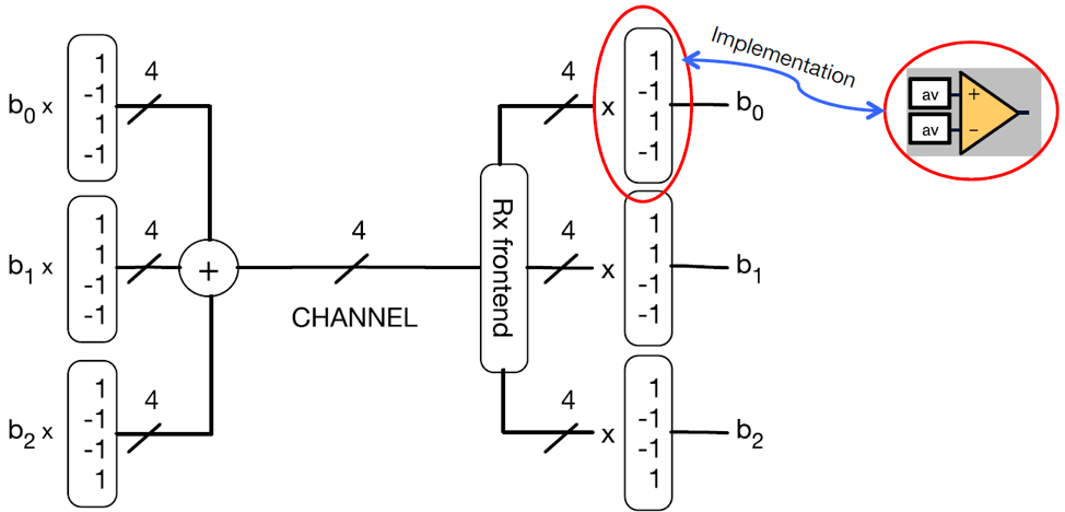
Fig. 6: This shows three signals being multiplied by three mutually orthogonal vectors before being mixed on four lines. The received signal is again multiplied by those vectors to retrieve the binary signals. Source: Kandou
Kandou has several hundred coding schemes for various numbers of wires. For n wires, it claims that 2n-1 vectors will have ISI resilience, guaranteed mathematically.
Clocks also are carried across these links for recovery at the receiver. Because the receiver can look across all of the wires for transitions, the density may be sufficient to avoid any clock encoding. Alternatively, one of the wires could be designated as carrying the clock, with a traditional encoding scheme applied to guarantee enough transitions.
This approach also can increase bandwidth by using more than one level on a wire, as is done with PAM-4. But, unlike PAM-4, it doesn’t use all level combinations across all wires. In general, a single wire with n levels will carry log2n bits per symbol. In the PAM examples, PAM-4 carries two bits per symbol, while PAM-8 carries 3 bits. But with more wires, more combinations are available, and yet Kandou picks a smaller number to use. With one example involving 10 levels on each of 6 wires, it picks 32 out of the million possible combinations, giving 5 bits per symbol.
This approach does have one specific challenge. “The only enemy [Chord] has is skew,” said Shokrollahi. He said a number of patented de-skewing techniques were developed to deal with this. In a couple of examples, feedback from the receiver can be used to de-skew at the encoder prior to transmission. Alternatively, de-skew can be done in the receiver.
DFEs may or may not be needed on a given channel. If one is needed, Kandou says that it will have power lower than that used for PAM-4. Forward error correction (FEC) has been devised for Chord, but it’s not an intrinsic part. Start-up training to center the eyes may be needed on some channels, but may not be needed on others.
For short connections, Chord can be DC coupled. For longer connections, AC coupling is used. Controlling disparity for AC-coupled channels is not something that’s built into Chord, but there are coding schemes that can be used if disparity is a concern.
While Chord’s approach provides for many different implementations, each with some number of wires and some number of levels per wire, there are a few that have been commercialized. The most basic one is called Ensemble NRZ, or ENRZ, which carries 3 bits on 4 wires using quaternary (4-level) signaling. There are others, as well, with names like EP3L and CNRZ. They vary in terms of numbers of lines and levels on the lines (with some as high as 10 levels), but they share basic Chord characteristics.

Figure 7. ENRZ signaling, with three bits over four quaternary wires. Source: Kandou
The catch with Chord is that it is proprietary to Kandou. The Optical Interconnect Forum (OIF) has included Chord as a standard, so Kandou must make Chord available on a RAND – Reasonable and Non-Discriminatory – basis. That means it can (and does) charge for it (up-front and royalties), but that the charges can’t be outrageous or capricious.
Asay echoed the concern: “Will the industry want to pay royalties? That’s the biggest hold-up on it. Even over the next two years, the answer is no.”
The other possible hurdle is complexity. “If you have a very controlled environment, then you may use [Chord-like signaling], customize it, and take advantage of it,” said Sadr. “But interop is tough. [It’s] a mathematically sound solution, but it has struggled due to practicality. Folks prefer simplicity.”
 |
|
 |
 |
 |  |
 |  |
Leave a Reply